I’ve never worked on volumetric rendering before and thought I should try to expand my graphics programming repertoire. This article details my finding, specifically on the rendering side. A good part of the project also involves cloud shaping through composing different 2D and 3D noises. This requires another blog of its own, maybe at a later date.
When it comes to cloud rendering, everyone pretty much references these 3 well-known SIGGRAPH talks:
- The 2015 SIGGRAPH talk Advancements in Realtime Rendering by Guerrilla games going over their approach in Horizon Zero Dawn, arguably the article that propelled interest in the subject.
- The 2016 SIGGRAPH talk Physically-based Sky Atmosphere and Cloud Rendering on the Frosbite engine’s cloud rendering system. This one is more realistic and involves modeling distance to the sun as well as curvature of the earth, which are beyond the scope of my project.
- The 2017 NUBIS Authoring Realtime Volumetric Cloudscapes by Guerilla game that improves upon their previous system. I will also be referencing these.
Going with the theme of trying new things, I also learned Godot for this project. I had a lot of fun doing so. The shaders were very straightforward to write — all that’s needed is to specify a vertex and fragment function. It’s a far-cry from the amount of pipeline-specific options you need to specify for Unity and I would definitely reccommend it as the first engine to try out if you want to learn shaders.
Ray Marching
 Before being able to render clouds I needed to start with the basic of volumetric rendering: a ray
marcher.
I used Martin Donald’s Tutorial on Godot Raymarching
to first familiarize myself with the engine and experimented on my own after I got the hang of things.
The result is some hyperactive balls moving around in circles.
Before being able to render clouds I needed to start with the basic of volumetric rendering: a ray
marcher.
I used Martin Donald’s Tutorial on Godot Raymarching
to first familiarize myself with the engine and experimented on my own after I got the hang of things.
The result is some hyperactive balls moving around in circles.
shader_type spatial;
render_mode unshaded, depth_test_disabled;

uniform int MAX_STEPS = 100;
uniform float MAX_DIST = 100.0;
uniform float SURF_DIST = 0.01;
uniform float SMOOTHNESS = 0.1;

float union_quadratic( float a, float b, float k ) {
    k *= 4.0;
    float h = max( k-abs(a-b), 0.0 )/k;
    return min(a,b) - h*h*k*(1.0/4.0);
}

float signed_distance_sphere(vec3 point, vec3 sphere_center, float radius) {
	return length(sphere_center - point) - radius;
}

float get_distance_to_world(vec3 point) {
	vec3 spheres_pos[3] = vec3[](
		vec3(0.5, 0.7, 1.0),
		vec3(0.5, 0.2, -0.5),
		vec3(1, 1.1, 0.5)
	);
	float spheres_radius[3] = float[](.5, 1.0, 0.6);

	float dist = MAX_DIST;

	for (int i = 0; i < 3; i++) {
		vec3 noisy_movement = vec3(
			0.5 * sin(0.5 + TIME * 0.2 * 3.1415 * 2.0 * (float(i)+1.0)),
			0.5 * cos(0.5 + TIME * 0.4 * 3.1415 * 2.0 * (float(i)+1.0)),
			0.5 * sin(0.5 + TIME * 0.8 * 3.1415 * 2.0 * (float(i)+1.0))
		);

		vec3 sphere_pos_with_movement = spheres_pos[i] + noisy_movement;
		float distance_to_i_sphere = signed_distance_sphere(point, sphere_pos_with_movement, spheres_radius[i]);
		dist = union_quadratic(dist, distance_to_i_sphere, SMOOTHNESS);
	}

	return dist;
}

vec3 get_normal(vec3 point) {
	float distance_to_world = get_distance_to_world(point);
	vec2 error = vec2(0.01, 0.0);
	vec3 normal = distance_to_world - vec3(
		get_distance_to_world(point - error.xyy),
		get_distance_to_world(point - error.yxy),
		get_distance_to_world(point - error.yyx)
	);
	return normalize(normal);
}

float ray_march(vec3 ray_origin, vec3 ray_direction) {
	float marching_distance = 0.0;

	for (int i = 0; i < MAX_STEPS; i++) {
		vec3 current_position = ray_origin + ray_direction * marching_distance;
		float distance_to_closest_object = get_distance_to_world(current_position);

		marching_distance += distance_to_closest_object;

		bool is_far_from_origin = marching_distance >= MAX_DIST;
		bool is_step_too_small = distance_to_closest_object <= SURF_DIST;
		if (is_far_from_origin || is_step_too_small) break;
	}

	return marching_distance;
}

void vertex() {
	// Called for every vertex the material is visible on.
}

void fragment() {
	// Called for every pixel the material is visible on.
	vec3 position_worldspace = ((INV_VIEW_MATRIX * vec4(VERTEX, 1.0)).xyz);
	vec3 ray_origin = CAMERA_POSITION_WORLD;
	vec3 ray_direction = normalize(position_worldspace - ray_origin);

	float ray_distance = ray_march(ray_origin, ray_direction);

	ALPHA = step(ray_distance, MAX_DIST);

	vec3 normal = get_normal(ray_origin + ray_direction * ray_distance);
	ALBEDO = (normal + 1.0) / 2.0;
}
Lighting Model
Beer’s Law
Volumes scatter light. They behave very different from surfaces which I’m used to rendering. Beer’s law approximates how much light is transmitted based on the total amount of volume the light travels through. Let $r$ be a ray of light and $d(r)$ denote the distance it travels through our medium. Its transmittance, according to Beer’s law, is:
\[\begin{equation} \mathrm{Transmittance}(r) = e^{-a \cdot d(r)} \end{equation}\]where $a$ is a constant that depends on how dense the volume is and hence how well it disperses light.
I’m no physicist, but this makes a lot of sense mathematically. Suppose light travels through our volume and gets redirected with some constant probability over a fixed duration. This follows a Poisson distribution with respect to time, and the cumulative distribution is the same as Beer’s Law.
We can apply Beer’s law to the light traveling from behind the volume into our camera:
\[\mathrm{Luminance}_{c}(r) = \mathrm{Luminance}_{b}(r) * \mathrm{Transmittance}(r) + (1 - \mathrm{Transmittance(r)}) \cdot \mathrm{CloudColor}\]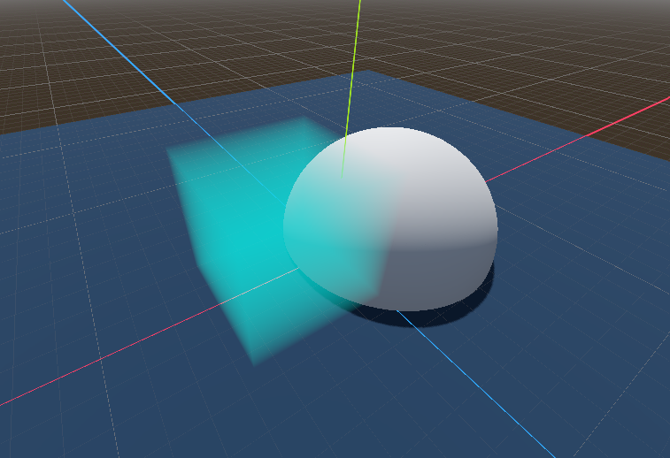 If we use the default blend mode for transparent materials
($ \mathrm{SrcColor} * \mathrm{SrcAlpha} + \mathrm{DstColor} * (1 - \mathrm{SrcAlpha})$),
then all we need to do is set the cloud alpha to $1 - \mathrm{Transmittance(r)}$. Implementing this naively gives us the image on the right.
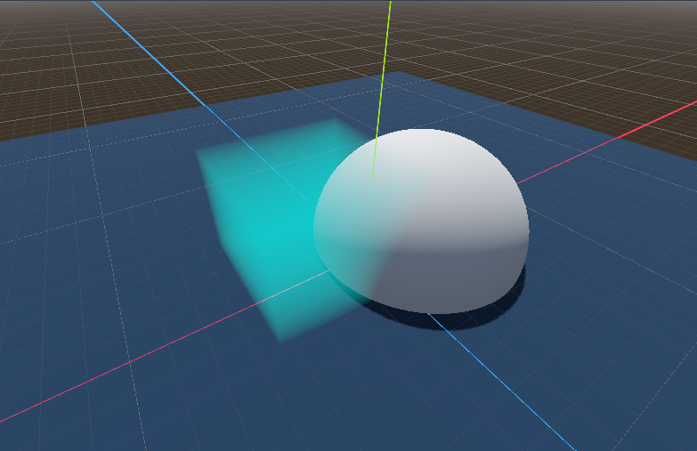 But we need to also factor in how our volume intersects with solid geometry.
We can do so by sampling the depth texture and account for it when raytracing the volume,
as well as cut off rendering if the object completely obscures our volume.
The result is the image to the right.
But we need to also factor in how our volume intersects with solid geometry.
We can do so by sampling the depth texture and account for it when raytracing the volume,
as well as cut off rendering if the object completely obscures our volume.
The result is the image to the right.
shader_type spatial;
render_mode unshaded, depth_test_disabled;

uniform sampler2D DEPTH_TEXTURE : hint_depth_texture, filter_linear_mipmap;

uniform vec3 BOUND_SIZE = vec3(5);
uniform vec3 BaseColor = vec3(0.0, 0.5, 0.5);
uniform float LightAbsorption = 1.0;

vec2 get_cube_penetration_distance(vec3 ray_origin, vec3 ray_direction, vec3 bound_center) {
    vec3 min_bound = bound_center - BOUND_SIZE / 2.0;
    vec3 max_bound = bound_center + BOUND_SIZE / 2.0;

    vec3 penetration_min_bound = (min_bound - ray_origin) / ray_direction;
    vec3 penetration_max_bound = (max_bound - ray_origin) / ray_direction;

    vec3 penetration_min = min(penetration_max_bound, penetration_min_bound);
    vec3 penetration_max = max(penetration_max_bound, penetration_min_bound);

    float entry_time = max(max(penetration_min.x, penetration_min.y), penetration_min.z);
    float exit_time = min(min(penetration_max.x, penetration_max.y), penetration_max.z);

    return vec2(max(0.0, entry_time), max(0.0, exit_time));
}

float get_linear_depth(float raw_depth, vec2 screen_uv, mat4 inv_projection_matrix) {
    vec3 clip_space_position = vec3(screen_uv * 2.0 - 1.0, raw_depth);
    vec4 hom_position_view_space = inv_projection_matrix * vec4(clip_space_position, 1.0);
    vec3 position_view_space = hom_position_view_space.xyz / hom_position_view_space.w;
    return -position_view_space.z;
}

void vertex() {
    // Called for every vertex the material is visible on.
}

void fragment() {
    float depth = texture(DEPTH_TEXTURE, SCREEN_UV).r;
    float linear_depth = get_linear_depth(depth, SCREEN_UV, INV_PROJECTION_MATRIX);

    // Probably should be in vertex shader
    vec3 position_worldspace = ((INV_VIEW_MATRIX * vec4(VERTEX, 1.0)).xyz);

    vec3 object_position_worldspace = (MODEL_MATRIX * vec4(vec3(0.0), 1.0)).xyz;

    vec3 ray_origin = CAMERA_POSITION_WORLD;
    vec3 ray_direction = normalize(position_worldspace - ray_origin);

    vec2 cube_peneration_times = get_cube_penetration_distance(
            ray_origin, ray_direction, object_position_worldspace);

    float enter_time = cube_peneration_times.x;
    float exit_time = min(cube_peneration_times.y, linear_depth);

    float distance_in_medium = exit_time - enter_time;
    float transmittance = exp(-distance_in_medium * LightAbsorption);

    ALBEDO = BaseColor;
    ALPHA = (1.0 - transmittance) * step(enter_time, linear_depth); // depth-based culling
}
Non Uniformity
Our Beer’s Law calculations assumes our volume is uniformly dense. In reality, the body of clouds are often varying in density. So the calculation looks something like this:
\[\begin{align} \mathrm{Transmittance}(r) &= e^{-a \cdot d(r)} \\ d(r) &= \int_{r} \mathrm{Density}(r) dr \end{align}\]I am going to use compositions of various 3D noise functions to model $\mathrm{Density}(r)$. Finding a closed form for this integral is difficult if not impossible. Instead, we resort to numerical integration. This is fancy speak for approximating an integral by converting it into a sum of small discrete parts.
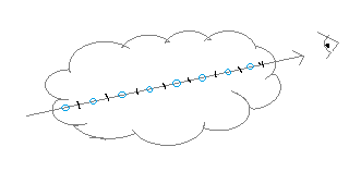 We break our ray into equal-sized parts and use one sample for each slice to approximate how much
volume the ray intersects. The result is:
We break our ray into equal-sized parts and use one sample for each slice to approximate how much
volume the ray intersects. The result is:
const int NUM_SAMPLES = 10;

// Beer's law
float get_absorption(float density, float absorption_coef) { return exp(-density * absorption_coef); }

void fragment() {
    ...
    float enter_distance = max(cube_penetration_distance.x, 0.0);
    float exit_distance = clamp(cube_penetration_distance.y, 0.0, real_linear_depth);

    float total_distance = (exit_distance - enter_distance);
    float segment_length = total_distance / float(NUM_SAMPLES);

    vec3 volumetricLightColor = vec3(0.0);

    float volume_absorption_from_march = 1.0;

    for (int sample = 0; sample < NUM_SAMPLES; sample++) {
        float segment_progress = (float(sample) + 0.5) / float(NUM_SAMPLES);
        float segment_midpoint_time = mix(enter_distance, exit_distance, segment_progress);
        vec3 midpoint_position = ray_origin + ray_direction * segment_midpoint_time;

        float segment_density = get_density(midpoint_position, object_position_worldspace);

        float previous_absorption = volume_absorption_from_march;
        volume_absorption_from_march *= get_absorption(segment_density * segment_length, AmbientAbsorption);

        float segment_absorption = previous_absorption - volume_absorption_from_march;

        volumetricLightColor += VolumeColor * AmbientColor * segment_absorption;
    }

    float transmittance = 1.0 - volume_absorption_from_march;

    ALBEDO = volumetricLightColor;
    ALPHA = transmittance * step(enter_distance, real_linear_depth);
}
For loops and if cases in shaders should raise some red flags. However, in this case it’s okay because we’re looping over a fixed amount of iteration, so all fragments intersecting with the cloud will execute the same instructions.
Readers might be nervous that we’re doing multiple samples per pixel. Our fragment shader will indeed get quite performance intensive as we add more details, enough to rule out lower-end hardware. However, high-end GPUs should be able to handle at least 1000 samples or more per pixel.
Lighting
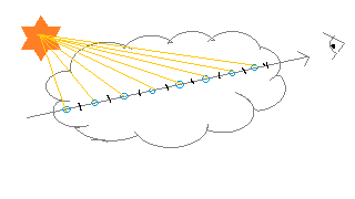 We’ve been treating clouds as if it has some inherent ambient lighting.
However, we also need to account for lighting from the sun.
For every sample we take for calculating Beer’s Law, we now calculate how much light from
the sun reaches it.
This also follows Beer’s Law, and we compute this by another round of numerical integration.
We’ve been treating clouds as if it has some inherent ambient lighting.
However, we also need to account for lighting from the sun.
For every sample we take for calculating Beer’s Law, we now calculate how much light from
the sun reaches it.
This also follows Beer’s Law, and we compute this by another round of numerical integration.
Since clouds mostly receives light from the sun, the correct approach is to use calculate with directional lights. However, for testing I went with a point light just so I can move it around and test.
const int NUM_SAMPLES = 10;
const int NUM_LIGHT_SAMPLES = 5;

float get_radiance_absorption(float density, float absorption_coef) {
    // Beer's Law
    float beer = exp(-density * absorption_coef);
    // Used to lighten the darkest parts of the clouds, as suggested by the Nubis paper
    float beer_scaled = exp(-density * absorption_coef * 0.25) * 0.7;

    return max(beer, beer_scaled);
}

float get_light_absorption(vec3 position, vec3 bound_center) {
    vec3 ray_origin = position;
    vec3 ray_direction = -LightDirection;

    if (dot(ray_direction, ray_direction) > 0.0) {
        ray_direction = normalize(ray_direction);
    }

    vec2 cube_penetration_distance = get_cube_penetration_distance(
            ray_origin, ray_direction, bound_center);

    float enter_distance = max(cube_penetration_distance.x, 0.0); // should be 0.0
    float exit_distance = min(max(cube_penetration_distance.y, 0.0), distance_to_light);

    float total_density = 0.0;
    float total_distance = (exit_distance - enter_distance);
    float segment_length = total_distance / float(NUM_LIGHT_SAMPLES);

    for (int sample = 0; sample < NUM_LIGHT_SAMPLES; sample++) {
        float segment_progress = ((float(sample)) / float(NUM_LIGHT_SAMPLES));
        float segment_midpoint_time = mix(enter_distance, exit_distance, segment_progress);

        vec3 midpoint_position = ray_origin + ray_direction * segment_midpoint_time;
        float segment_density = get_density(midpoint_position, bound_center);
        total_density += segment_density * segment_length;
    }

    return get_radiance_absorption(total_density, LightAbsorption);
}

void fragment() {
    ...
        for (int sample = 0; sample < NUM_SAMPLES; sample++) {
            ...
            float light_absorption = get_light_absorption(midpoint_position, object_position_worldspace);
            volumetricLightColor += VolumeColor * LightColor * light_absorption * previous_absorption
                * segment_length;
            ...
        }
    ...
}
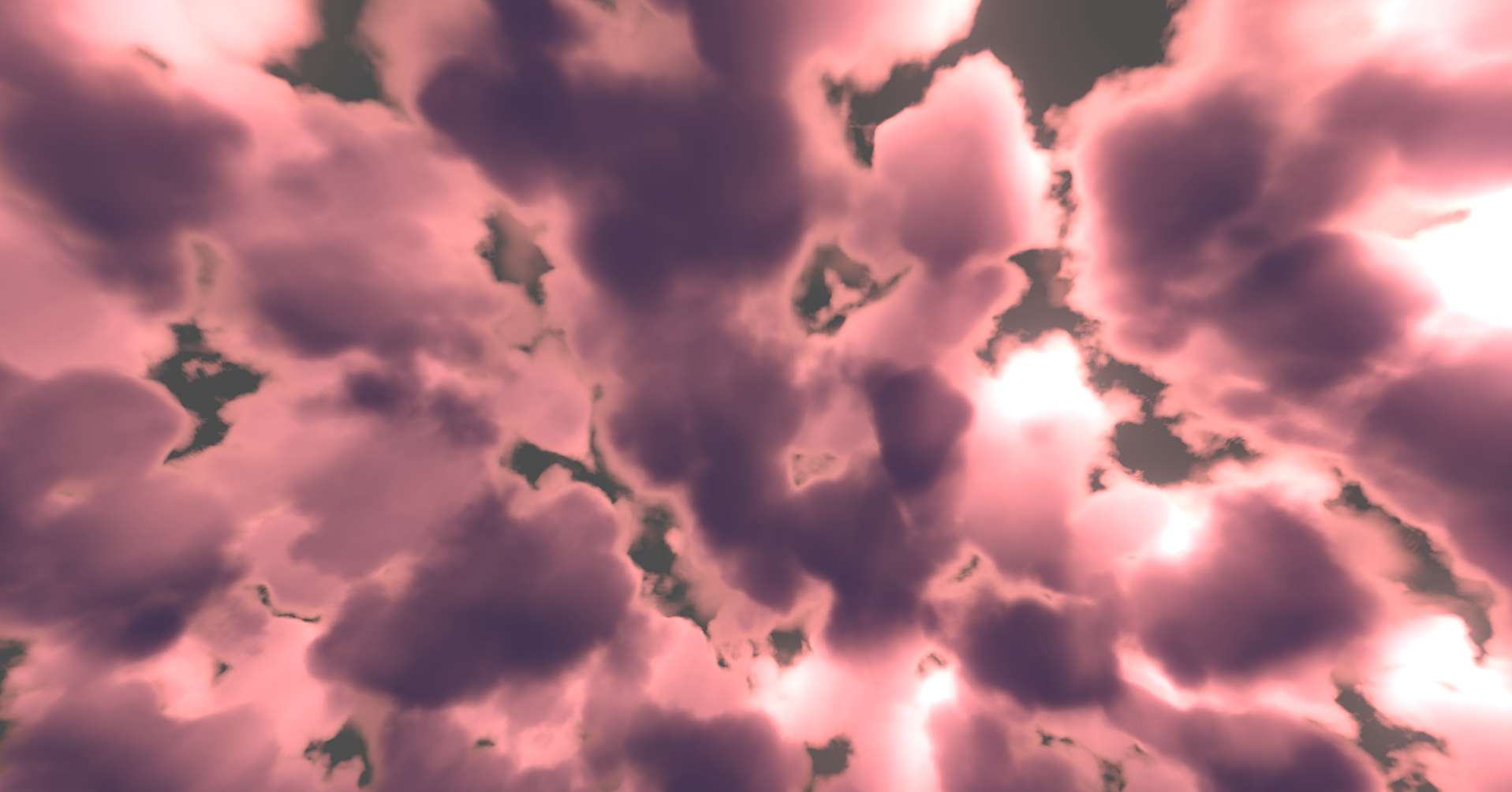
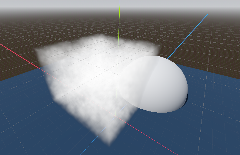
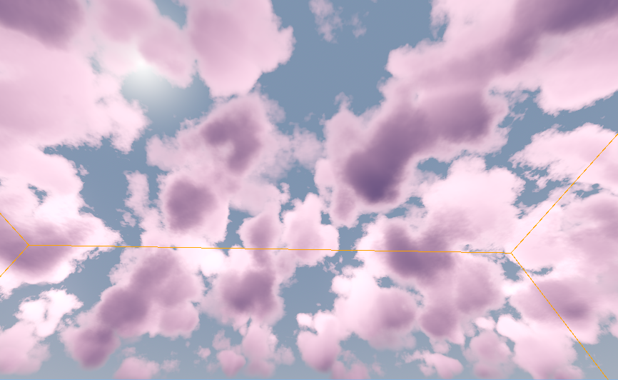
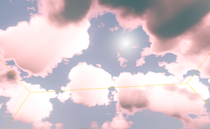 After cloud shaping and some tweaking, I got a decent looking result.
This version of the code runs with
After cloud shaping and some tweaking, I got a decent looking result.
This version of the code runs with NUM_SAMPLES = 64 and NUM_LIGHT_SAMPLES = 32 and still manage to run smoothly, which goes to
show how powerful modern GPUs can be.
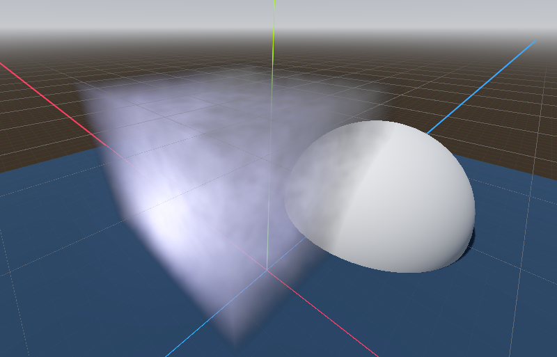
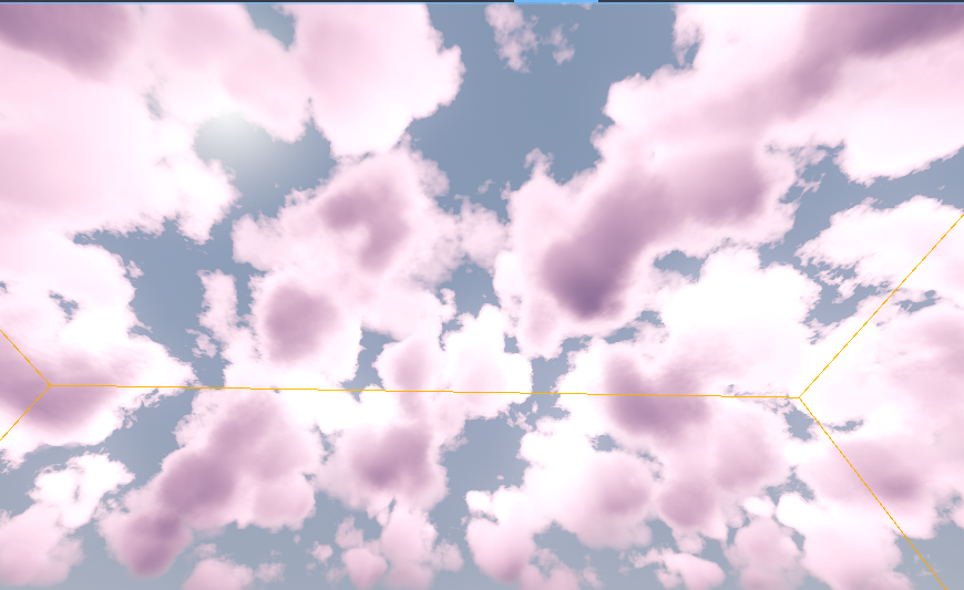
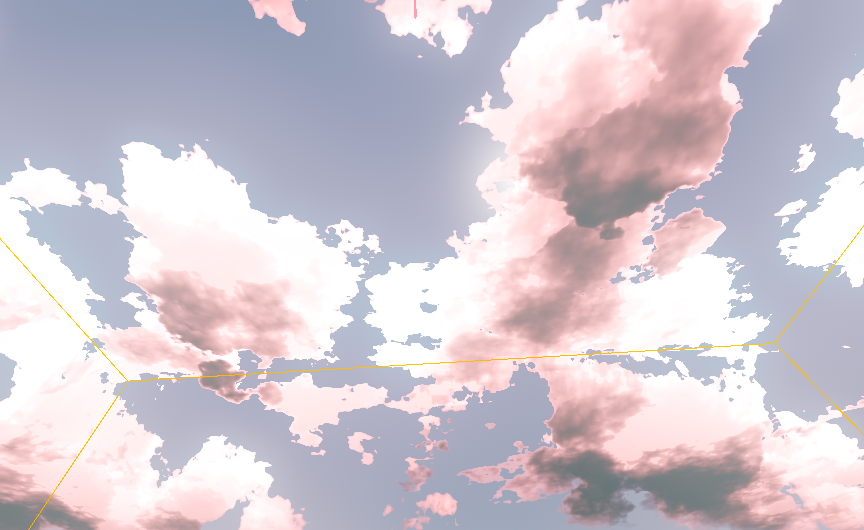 Decreasing these values down to 16 would yield almost the same result, but further decreases will introduce
color banding and some sampling artifacts. The right image shows what happens when you reduce both down to 4.
Decreasing these values down to 16 would yield almost the same result, but further decreases will introduce
color banding and some sampling artifacts. The right image shows what happens when you reduce both down to 4.
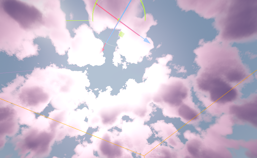
Anisotropic Scattering
So far, our lighting model assumes that light scatters uniformly in all directions. However, in reality light has a slight bias in favor of scattering forward.
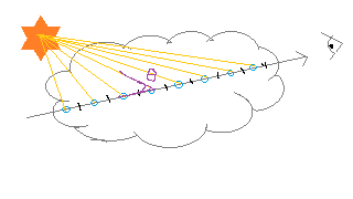 One way we can model this is through a phase function, which is a type of BSDF
that only takes into account $\theta$, the angle between the incoming and outgoing light.
We take this into account when calculating the radiance of a particular sample on our ray between
the camera and pixel position. Previously, we were using:
One way we can model this is through a phase function, which is a type of BSDF
that only takes into account $\theta$, the angle between the incoming and outgoing light.
We take this into account when calculating the radiance of a particular sample on our ray between
the camera and pixel position. Previously, we were using:
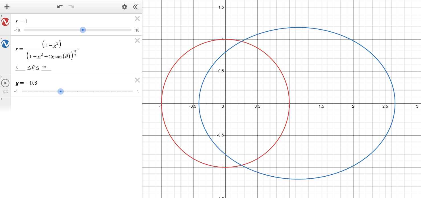
A widely common phase function we can use instead is the Henyey Greenstein, proposed in 1941.
\[\begin{equation} r(\theta) = \frac{1}{4\pi} \frac{1 - g^2}{(1 + g^2 + 2g\cos(\theta))^{\frac{3}{2}}} \end{equation}\]$g$ here controls the scattering bias. -1 means fully biased towards backwards scattering, and 1 means fully biased towards forward scattering.
// Henyey-Greenstein anisotropic scattering
float get_phase_function(float cosTheta) {
    float g = LightingAsymmetry;

    float normalizing_factor = 1.0 / (PI * 4.0); // can be precomputed on the CPU
    float denominator = 1.0 + g * g + 2.0 * g * cosTheta;
    float numerator = (1.0 - g * g);

    return normalizing_factor * numerator / pow(denominator, 1.5);
}

float get_light_absorption(vec3 position, vec3 bound_center) {
    ...
    float cosLightTheta = -dot(ray_direction, eye_direction);
    float phase_function = get_phase_function(cosLightTheta);

    return get_radiance_absorption(total_density, LightAbsorption) * phase_function;
}
Closing Note
From this point there’s a lot of directions I can take the project. Some of these includes:
- Following the NUBIS paper’s suggestion and implement their improved powder effect. This effectively accounts for the observation that regions deep inside the cloud accumulates more redirected light.
- Optimizing our sampling method to take larger step sizes where the volume’s density is low.
- Model a physically based sky and curves the render box, effectively modelling earth’s curvature.
- Using a different phase function so that you get both forward scattering and a little bit of backwards scattering.
- Implement a post processing god ray effect.
But I decided to stop there as going much further from this point will involve a lot of tweaking and polishing that’s beyond what’s neccessary for a toy project.